(back
to Sound Design home)
Louisiana Tech University
School of the Performing Art’s
Stone Theatre
Sound Control Manual
Table of Contents
Section I- Explanation
and Concise Descriptions
Section II- Diagrams
Figure I.I- Soundboard
Input Channels
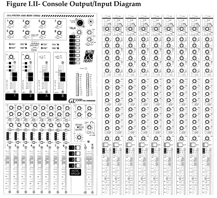
Figure I.II- Soundboard
Output Channels
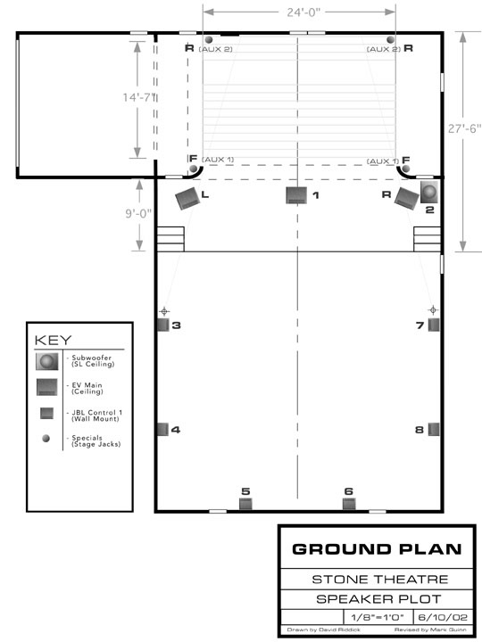
Figure I.III- Speaker
Placement Diagram
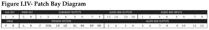
Figure I.IV- Patch
bay Diagram
Prepared June 10, 2002 by Michael RasburyUniversity Theatre Sound; Installed
2001
Reasons for the new sound system
The sound system was designed and installed in 2001 by Michael Rasbury and
American Audio. The previous system was comprised of pieced-together
public address equipment not necessarily intended for theatrical use. The
previous system had a maximum of six amplified channels of audio, two of these
controllable via auxiliary potentiometers. Our theatre had no digital
signal processing capabilities.
Our playback equipment was mainly comprised of consumer mini-disc players,
cassette decks and consumer compact disc players. Only our audio amplifiers
were considered professional gear. Since our goal is to prepare students
for the technical requirements of the professional theatre, we felt it a necessity
to improve our facilities.
The new design allows the user to compose and playback audio and music from
one or more of several approaches. The system remains conventional by
retaining traditional playback devices such as mini-disc, cassette and compact
disc players. However, we have added several computer-based components
that can be interfaced with the more traditional equipment. Additionally,
we have expanded our original six channels of audio to twelve channels of amplified
audio. Digital signal processing capabilities (outside of the computer
environment) were also added. Finally, we improved our backstage monitoring
system in the University Theatre and in Howard Auditorium. All of the
new equipment meets professional standards.
Components of the new sound system
Our new system allows the user to approach a design from one or more of three
perspectives. The first approach allows the sound designer to create
and playback cues using the conventional method of two-track playback devices
such as the mini-disc, cassette and compact disc player/recorders. These
devices can then be “mixed” using our twenty-four-channel console
and routed to one or more of our twelve amplified channels of audio.
The second application allows the user to use the Richmond Sound Design Audio
Box 1616 for audio playback. This device is basically a sixteen channel/track
automated matrix mixer that also triggers 48 kHz stereo wave files via internal
hard drive. This device represents the more recent trends in audio. Since
it is fully automated, an entire design can be programmed into it and triggered
on playback automatically similar to the lighting designer’s two-scene
preset lighting controller.
The third approach uses the PowerMac G4 Digital Audio Workstation as a playback
device. The computer is connected to a Mark of the Unicorn 828 Firewire
Input/Output device. This rack-mounted device has eight balanced quarter-inch
outputs. The sound designer can use Digital Performer and other audio
software to assign audio files to one or more of the 828’s outputs. The
outputs can then be connected with an eight channel audio snake to eight inputs
on the board and assigned to separate speakers. The eight outputs may
also be directly patched to our amplified channels using a special quarter-inch
TRS to TFT patch cable.
How to use this manual
This manual is not intended to be comprehensive. An overview of each
section of the system is included with references to attached diagrams and
descriptions of the respective equipment’s owner’s manuals.
Turning on the System
The system has a switch that controls the order of equipment power up. It
is located in the rack to the operator’s left in the middle in the rack. This
method for “powering up” protects the speakers from system “spikes.” Upon
completion of a session, turn this switch off and the system will be “powered
down.”
Perspective One: The Traditional Approach
To use the new system conventionally, use the two-track playback equipment
located to the left in the audio rack. Two compact disc players and two
mini-disc players are directly connected to the soundboard and labeled accordingly. These
devices are connected to channels seventeen through twenty-four located to
the right of the group output faders. These channels can be panned left
or right and assigned to any of the soundboard’s outputs via the assignmentbuttons
located on each channel. The outputs of the soundboard are connected
to the top half of the patch pay (located in rack; see attached diagram, I.IV.) To
assign these outputs to the amplifiers requires no patching since each patch
location if fully “normaled” to the respective amp input below. Using
patch cables, it is possible to connect any soundboard output to any amplifier
input and consequently on to the speakers.
In the rack, there is a Lexicon Digital Signal Processor. The DSP’s
inputs are fed via the soundboard’s auxiliary outputs and are labeled
clearly on the console. The DSP’s outputs are directly connected
to channels fifteen and sixteen on the soundboard. These inputs can then
be assigned to any of the soundboard’s outputs via the assignment buttons
located on each channel (see attached diagram; I.I and I.II.)
Perspective Two: Richmond Sound Design’s Audiobox 1616HD
This approach uses the “Audiobox” as a master playback device. This
device is located on the ledge of the booth under the printer. This device
has sixteen inputs, available as patchable inputs on the patch bay; and sixteen
outputs, also located on the patch bay. To connect the Audiobox’s
outputs to the amplifiers, patch cables must be used with the patch bay. The
Audiobox requires the use of dedicated computer software for operation.
To sound design using this system, your sound cues must be converted to 48
kHz, 16 bit wave files. Digital Performer allows the designer to convert
sound cues to this format (see pages … in Digital Performer’s user
manual.) The sound cues must then be “uploaded” to the Audiobox
via AB Loader software located on the computer. This piece of software
is utilitarian, requiring the user to select a range of wave files and “upload” them
to the Audiobox.
Once the Audiobox has been loaded with wave files, another piece of software
called ABControl must be used to control the Audiobox. This program makes
use of several windows: a playback control window, a virtual console of assignable
inputs, a virtual console of outputs, wave file list and digital signal processing
windows. Using this software requires the application of standard sound
mixing practices. Having knowledge of traditional sound mixing makes
this piece of software very easy to use. Basically, a wave file is “attached” to
one or more of sixteen input channels, and then assigned in a traditional fashion
to one or more of sixteen outputs. On the virtual input console, traditional
panning, equalization, volume and digital signal processing can be set and
stored in the computer as a “captured” cue. The total design
can then be saved as a sequence of these “captured” cues as a file
for use with a production. Playback of the design requires a single software
button push for each cue (much like the lighting designer’s two-scene
preset.)
Both the list of uploaded wave files and the cue files can be saved for archival
purposes. This device represents some of the more current applications
of Sound Design for production.
Perspective Three: Using the MOTU 828 as a playback device
The Mark of the Unicorn’s 828 Audio Interface can be used in conjunction
with the mini-disc and compact disc players. The sound designer can use
an eight-channel quarter-inch multi-cable to connect the outputs of the 828
directly to available channels on the sound console. These inputs are
assignable to the output faders and in turn to the separate speakers. Of
course, the user can use a multi-cable to connect the 828 directly to the
amplifier inputs on the patch bay.
Earlier, I likened the Audiobox to a two-scene preset in lighting. This
application of the MOTU 828 is similar to a single “scene.” Digital
Performer will not let the user establish a list of sound cues to cross fade
between in real time. This software is traditionally used by musicians
for the creation of MIDI and audio files. We use this software to compose
sound effects as well.
In Digital Performer, the designer can assign each virtual track to one or
more of the eight outputs on the 828 Audio Interface. The interface converts
the digital information into an analog signal for mixing. This method
works particularly well for surround applications while retaining stereo recordings
for mini-disc playback. The 828 becomes a playback device.
The Mark of the Unicorn 828 Firewire Audio Interface
Sound InputThe MOTU 828 serves as an audio input and output device for the
Macintosh G4 computer. This piece of hardware has limited volume controls
for input and output on the front of the device. It also has important
features that are only accessible via a software control panel, located on
the computer in the “control panels” folder. Using this “828” control
panel, the user can set the sample rate, clock source, input and output routings
and digital input and output settings. To record audio using the 828
interface, digital audio software is required to record inputs.
To record an audio source, connect an audio signal to any of the eight inputs
on the back of the device. There are gain potentiometers on the
front of the 828 to set the amount of audio to be recorded by Digital Performer.
This is half the process. Open Digital Performer and create a new document. Choose
a stereo or mono track to record on. There is a section on each track
for setting an input. Click in this area and choose the inputs that are
currently connected from the pop-up menu. This will tell Digital Performer
to “look for” audio signals at the inputs selected on the MOTU
828. In the “windows” menu within Digital Performer, select “audio
monitor” to see the level being received by the computer. Start
playing the audio intended for recording. If an indication of clipping
(red indicators) is present in the audio monitor window, decrease the input
volume using either the control of the signal source or input gain on the MOTU
828. Now that proper audio levels have been established, press the record
button on Digital Performer. Record mode is not activated if the record
icon on the respective track is not selected. To playback the recording,
each track within Digital Performer must have an output assignment. This
assignment sends the audio out of the 828’s corresponding outputs.
Sending Audio to the Backstage Monitors
The backstage monitors receive audio from a distribution amplifier located
in the rack of amplifiers at the end of the booth. The amplified signal
travels a physical toggle switch panel located upstage right on Howard Stage. The
toggle switches located on the panel have three positions, Howard, UT, and
off. Each switch is labeled with the room number the switch represents. When
in the “UT” position, sound may be sent from the University Theatre’s
soundboard to the distribution amp located in the University Theatre booth. When
in the “Howard” position, the soundboard and distribution amp
in Howard control the signal being sent.
In each respective booth, there is a cable labeled “monitors.” Choose
an output on the soundboard such as an auxiliary output to send a signal the
distributionamp. The cable labeled “monitors” is connected
directly to the distribution amplifier in both the University Theatre and
Howard Auditorium booths.
However, the backstage monitors may be used without the soundboard. The
distribution amplifier has multiple channels. The cable labeled “monitors” is
directly connected to channel one. A permanently placed microphone can
be connected to channel two, scene each channel has a dedicated microphone
preamp. As long as the distribution amp is “powered up,” the
microphone’s perspective will be broadcast to the entire system.
Conclusions
I will add other applications to this manual as we discover them. For
now, I have attached copies of the owner’s manuals for each component. You
should refer to them for more detail. Please review the speaker placement,
console inputs, console outputs and patch bay diagrams for further detail.
2002 Michael Rasbury, School of the Performing Arts
Attachments include-
Section II- Diagrams
Figure I.I- Soundboard Input Channels
Figure I.II- Soundboard Output Channels
Figure I.III- Speaker Placement Diagram
Figure I.IV- Patch bay Diagram